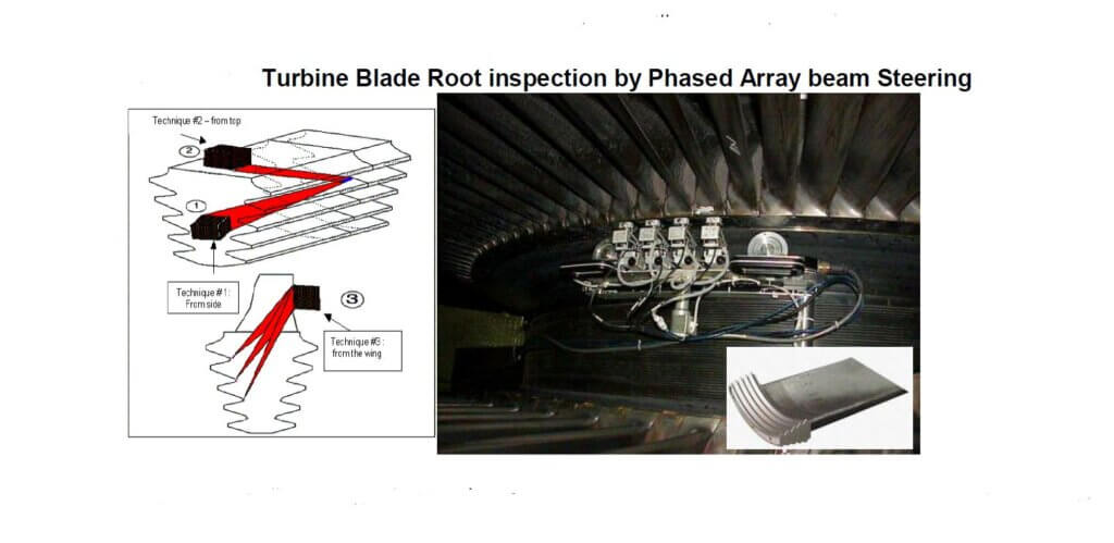
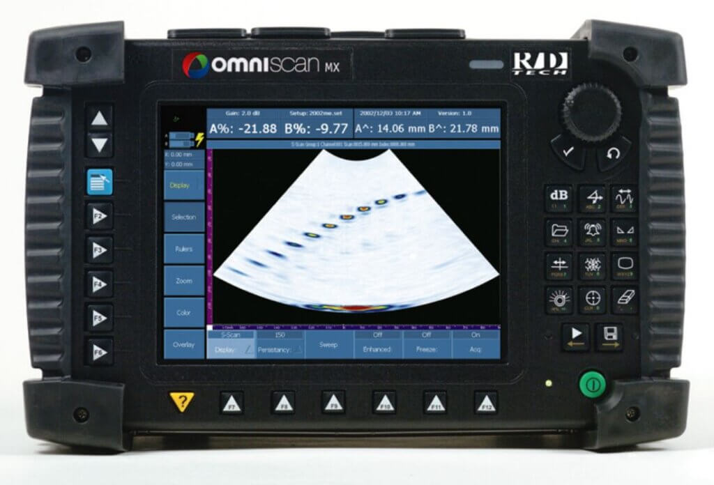
UT – Ultrasonic testing is used to test a variety of both metallic and nonmetallic products, such as welds, forgings, castings, sheets, tubing, plastics (both fiber-reinforced and unreinforced), and ceramics. Ultrasonic testing is capable of revealing the subsurface discontinuities in a variety of dissimilar materials, hence it is one of the most effective tools available to quality assurance personal. Conventional ultrasonic transducers for NDT commonly consist of either a single active element that both generates and receives high- frequency sound waves, or two paired elements, one for transmitting and one for receiving. Phased Array Ultrasonic Testing (PAUT) is an advanced ultrasonic technique that permits the shaping and steering of the ultrasonic beam angles, dynamic depth focusing and enhanced beam coverages. The Phased Array beam sweeps like a searchlight through the object, resulting in a recordable image that reveals defects hidden inside a structure or weld;
To learn more about conventional Ultrasonic testing read our Blog :
What Is a Phased Array System?
Phased array probes typically consist of a transducer assembly with 16 to as many as 256 small individual elements that can each be pulsed separately . These can be arranged in a strip (linear array), 2D matrix, a ring (annular array), a circular matrix (circular array), or a more complex shape. As is the case with conventional transducers, phased array probes can be designed for direct contact use, as part of an angle beam assembly with a wedge, or for immersion use with sound coupling through a water path.
Transducer frequencies are most commonly in the 2 MHz to 10 MHz range. A phased array system also includes a sophisticated computer-based instrument that is capable of driving the multielement probe, receiving and digitizing the returning echoes, and plotting that echo information in various standard formats.
Unlike conventional flaw detectors, phased array systems can sweep a sound beam through a range of refracted angles or along a linear path, or dynamically focus at a number of different depths, thus increasing both flexibility and capability in inspection setups.

How Does Ultrasonic Phasing Work?
In the most basic sense, a phased array system utilizes the wave physics principle of phasing. It varies the time between a series of outgoing ultrasonic pulses in such a way that the individual wavefronts generated by each element in the array combine with each other. This action adds or cancels energy in predictable ways that effectively steer and shape the sound beam. This is accomplished by pulsing the individual probe elements at slightly different times.
The main feature of phased array ultrasonic technology is the computer controlled excitation (amplitude and delay) of individual elements in a multielement probe.
The excitation of piezocomposite elements can generate an ultrasonic focused beam with the possibility of modifying the beamparameters such as angle, focal distance, and focal spot size through software. The sweeping beam is focused and can detect in specular mode the misoriented cracks. These cracks may be located randomly away from the beam axis.
There are three major computer-controlled beam scanning patterns
• Electronic scanning: the same focal law and delay is multiplexed across a group of active elements ; scanning is performed at a constant angle and along the phased array probe length (aperture). This is equivalent to a conventional ultrasonic transducer performing a raster scan for corrosion mapping or shear wave inspection. If an angled wedge is used, the focal laws compensate for different time delays inside the wedge.
• Dynamic depth focusing, or DDF (along the beam axis): scanning is performed with different focal depths. In practice, a single transmitted focused pulse is used, and refocusing is performed on reception for all programmed depths.
• Sectorial scanning (also called azimuthal or angular scanning): the beam is moved through a sweep range for a specific focal depth, using the same elements; other sweep ranges with different focal depths may be added. The angular sectors may have different values.

Phased array probes are functionally categorized according to the following basic parameters:
- Type – Most phased array probes are of the angle beam type, designed for use with either a plastic wedge or a straight plastic shoe (zero- degree wedge), or delay line. Direct contact and immersion probes are also available.
- Frequency – Most ultrasonic flaw detection is done between 2 MHz and 10 MHz, so most phased array probes fall within that range.
- Number of elements – Phased array probes most commonly have 16 to 128 elements, with some having as many as 256.
- Size of elements – As the element width gets smaller, beam steering capability increases, but large area coverage requires more elements at a higher cost.

Phased Array Wedges
Phased array probe assemblies usually include a plastic wedge. Wedges are used in both shear wave and longitudinal wave applications, including straight beam linear scans. These wedges perform basically the same function in phased array systems as in conventional single element flaw detection, coupling sound energy from the probe to the test piece in such a way that it mode converts and/or refracts at a desired angle in accordance with Snell’s law. While PAUT systems do utilize beam steering to create beams at multiple angles from a single wedge, this refraction effect is also part of the beam generation process. Shear wave wedges look very similar to those used with conventional transducers, and like conventional wedges they come in many sizes and styles. Some of them incorporate couplant feed holes for scanning applications. Some typical phased array probe wedges are seen in Figure 2-45.

Basics of PAUT Imaging
Phased array instruments, on the other hand, are naturally multichanneled as they need to provide excitation patterns (focal laws) to probes with 16 to as many as 256 elements. Unlike conventional flaw detectors, phased array systems can sweep a sound beam from one probe through a range of refracted angles, along a linear path, or dynamically focus at a number of different depths, thusincreasing both flexibility and capability in inspection setups. This added ability to generate multiple sound paths within one probe, adds a powerful advantage in detection and naturally adds the ability to “visualize” an inspection by creating an image of the inspection zone. Phased array imaging provides the user with the ability to see relative point-to-point changes and multiangular defect responses, which can assist in flaw discrimination and sizing. While this can seem inherently complex, it can actually simplify expanding inspection coverage with increased detection by eliminating the complex fixtures and multiple transducers that are often required with conventional UT inspection methods.
The following sections further explain the basic formats for conventional and phased array data presentation.
- A-Scan Data
- Single Value B-Scans
- Cross-sectional B-Scans
- Linear Scans
- C-Scans
- S-Scans
- Combined Image Formats
- Scanning Patterns
Reliable defect detection and sizing is based on scan patterns and specific functional combinations between the scanner and the phased array beam. The inspection may be:
- automated: the probe carrier is moved by a motor-controlled drive unit;
- semiautomated: the probe carrier is moved by hand, but the movement is encoded; or
- manual (or free running): the phased array probe is moved by hand and data are saved based on acquisition time(s).
Phased Array Instrumentation
- Pulser and receiver Parameters that largely define the operating range of transducers that can be used with the instrument
- Measurement and display
- Sizing options
- Inputs and outputs
Advantages of Phased Array as Compared with Conventional UT
Ultrasonic phased array systems can potentially be employed in almost any test where conventional ultrasonic flaw detectors have traditionally been used.
- Weld inspection and crack detection are the most important applications, and these tests are done across a wide range of industries including aerospace, power generation, petrochemical, metal billet and tubular goods suppliers, pipeline construction and maintenance, structural metals, and general manufacturing. Phased arrays can also be effectively used to profile remaining wall thickness in corrosion survey applications.
- The benefits of phased array technology over conventional UT come from its ability to use multiple elements to steer, focus, and scan beams with a single probe assembly.
- The potential disadvantages of phased array systems are a somewhat higher cost and a requirement for operator training. However, these costs are frequently offset by their greater flexibility and a reduction in the time needed to perform a given inspection.
- An array is an organized arrangement of large quantities of an object. The simplest form of an ultrasonic array for NDT would be a series of several single element transducers arranged in such a way as to increase inspection coverage and/or the speed of a particular inspection.
- Examples of this include: Tube inspection, where multiple probes are often used for both crack detection, finding laminar flaws, and overall thickness measurement.
- Forged metal parts, which often require multiple probes focused at different depths to enable the detection of small defects in a zonal manner.
- A linear arrangement of probes along a surface to increase detection of laminar flaws in composites or corrosion in metals.

References:
- PHASED ARRAY ULTRASONIC TESTING OF WELDS by NDT INTERNATIONAL PRIVATE LIMITED.
- Feature Image : Olympus Omni-Scan

Great blog! Easy to understand content about ultrasonic testing. Great work!