Each NDT Method is a vast subject and hence can’t be covered in one Article hence we will be learning about each method in multiple articles so that the articles don’t become overloaded and too long to refer and study. In this Article Equipment used in Ultrasonic Testing, we will learn about different equipment used in Ultrasonic Testing.
In the article Introduction to Ultrasonic Testing, we got familiarized with the basics of ultrasonic testing. In this article, we will learn about
- the equipment used to carry out Ultrasonic Testing
- Their internal components
- Their function and role in the Ultrasonic test.
Definitions
Pulse is a short wave train of mechanical vibrations.
echo: indication of reflected energy.
Pulse echo method: an inspection method in which the presence and position of a reflector are indicated by the echo amplitude and time.
Ultrasonic Flaw Detector
It generates and displays an ultrasonic waveform that is interpreted by a trained NDT operator, often with the aid of analysis software, to locate and categorize flaws in test pieces.
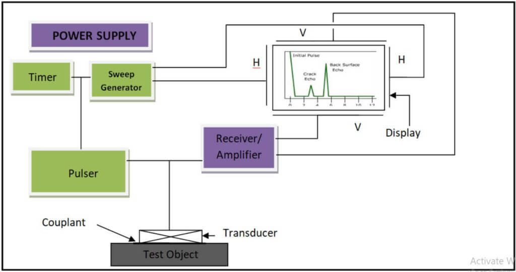
It typically includes an ultrasonic pulser/receiver, hardware and software for signal capture and analysis, a waveform display, and a data logging module.
These days ultrasonic flaw detectors are small, portable, microprocessor-based instruments suitable for both shop and field use.
Most of the general use ultrasonic flaw detectors work on Pulse Echo Instrumentation Electronics having similar electronic circuitry performing similar basic functions.
Power Supply
- Electrical power is provided from the line of supply or from a battery in the case of Portables UFD.
- Usually controlled by on/off switch and a fuse.
- Time delay devices protect the circuit elements during instrument warm-up.
- Circuits to supply power in all the components.
Transducer
- A transducer is a device that converts energy from one form to another.
- An ultrasonic transducer consists of a thin piezoelectric disk and its holder.
- The piezoelectric disk converts the electrical energy to ultrasonic energy and introduces vibrations into the test object.
- It also receives reflected ultrasonic vibrations from within the test object and converts them into electrical signals for amplification and display.
Pulser/ Receiver
- The pulser/pulse generator is the source of short high energy bursts of electrical energy (triggered by timer) that are applied to the transducer.
- Reflected pulses from the test object are received by the transducer, sent to the receiver, amplified and routed to the display unit.
- The amplifier amplifies the received signal from the transducer which can be calculated using the equation.

Where H2 and H1 are different echo heights
Decibel (dB): twenty times the base-ten logarithms of the ratio of two ultrasonic signal amplitudes, dB = 20 logs 10 (amplitude ratio).
Sweep Generator:
it sets a horizontal line (Time baseline) on the display to represent the thickness of the test item. HH and VV are two sets of electrodes. If voltage is applied on HH(Horizontal Deflection Plates)plates the beam will deflect horizontally and a voltage on VV(Vertical deflection Plates) plates will deflect the beam vertically.
Display and Timer:
In today’s ultrasonic testing devices flat panel display screens are used. Earlier in the 1990s oscilloscope cathode ray tubes were used.In both types of display, units are interrogated with a sweep generator and the controls required to provide a visual image signal received from the object.
The timer/rate generator/ Clock control all the timing signals to the pulser.The number of times the pulses are emitted is called pulse repetition frequency or pulse repetition rate (PRF). Normally a PRF of 100 to 1000 per second is used.
Transducers/Probe/Search unit:
a device that converts variations in a physical quantity, such as pressure or brightness, into an electrical signal, or vice versa. It is an essential component in ultrasonic testing. It is a combination of several elements performing many functions.
The prefix piezo is derived from the Greek word meaning “to press”. When mechanical pressure is applied to a piezoelectric material, the crystalline structure produces a voltage proportional to the pressure.
Piezoelectricity is a property of certain crystalline materials. Quartz, Rochelle, tourmaline, lithium sulfate, cadmium sulfide, and zinc oxide are naturally occurring piezoelectric materials. Polarized ceramic transducers like Barium titanate and lead zirconate titanates and lead meta niobate are artificially manufactured piezoelectric material also known as PZT materials.
Frequency of probes :
frequency (pulse repetition): the number of times per second an electro-acoustic search unit is excited by the pulse generator to produce a pulse of ultrasonic energy. This is also called the pulse repetition rate.
Mostly ultrasonic testing is performed using frequencies between 0.2 and 25MHz, with contact testing generally limited to 10 MHz and below because crystals ground for use above 10 MHz is too thin and fragile for practical contact testing.
Transducer frequency and crystals thickness are integrally related: the thinner the crystal, the higher the frequency.
- Higher the frequency, greater the sensitivity, and resolution, but attenuation is also greater and the penetration is poor.
- Lower the frequency, deeper the penetration, and less the attenuation but greater beam spread, less the sensitivity, and resolution.
- The sensitivity of a transducer is given by


Types of probe:
Normal Probe
- It used to transmit longitudinal waves into the test object.
- Here single transducer acts as both transmitter and receiver.
- Dia. 10mm,4 MHz and Dia 24mm, 2 MHz are general-purpose Normal Probes.
- It can be used for raw material inspection, an inspection of Slightly rough thickness. It is not advised to use the normal probe for very thin components because of the dead zone.
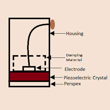
The dead zone is a zone where it is not possible to detect defects. Spherical waves interfere with each other and result in a system of maxima and minima in intensity in the region close to the transducer. This region is known as the near field region or Fresnel zone
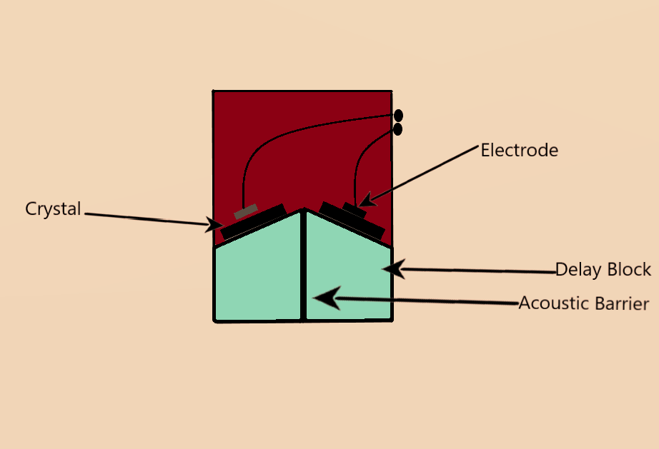
TR (Transmitter/Receiver) probe:
- Used to transmit longitudinal waves into the test object.
- It is a dual crystal transducer useful to test objects that are of relatively less thickness(less than 25mm) since it doesn’t have any dead zone.
- One crystal acts as a transmitter and other act as a receiver.
- Dia 10 mm, 4 MHz and Dia 24 mm, 2 MHz are commonly used TR probes.
Angle probe:
When the ultrasonic beam incident at an angle to the interface the reflected wave is also at an angle to the surface.
Snell’s Law: the angle of incidence is equal to the angle of reflection.
When the ultrasonic beam incident at an angle, the transmitted beam undergoes an abrupt change in the direction and this phenomenon is called Refraction.
But it is observed that the reflected wave and refracted wave consist of two components one of longitudinal mode and other of shear mode. This phenomenon is known as the Mode of Conversion.
In an Angle probe, the transducer is placed at a predetermined angle using a Perspex wedge to generate Shear waves.

Angle probe is used for inspection of plates, castings, and welds.
Generally used Angle probes are 8×9 mm, 4 MHz and 20 x 22mm, 2 MHz with the angle of reflection 450, 600 and 700.
NDT Advice: Use greater angle for less thickness and less angle for high thickness, because less thickness and less angle lead to the high dead zone and vice versa making the test less sensitive.
COAXIAL CABLES:
It is a type of electrical cable that has an inner conductor surrounded by a tubular insulating layer, surrounded by a tubular conducting shield. Many coaxial cables also have an insulating outer sheath or jacket. The term coaxial comes from the inner conductor and the outer shield sharing a geometric axis.
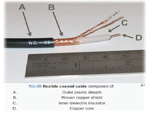
Connectors are attached at both ends of Co-axial cable and connect the UFD with Probe

BNC 
Mini Lemo 
UHF 
Micro Dot
COUPLANT
If a transducer is placed in contact with the surface of a dry object, very little energy is transmitted through the interface into the material because of the presence of air between the transducer and test material.
A Couplant is used is applied between the transducer face and the test surface to ensure efficient sound transmission from the transducer to the test surface.
Selection of Couplant depends upon
- The surface finish of the test specimen.
- The temperature of the test specimen.
- Possibility of chemical reactions between the test specimen and the couplant.
- Cleaning requirement
- Position of the test specimen.
Commonly used Couplants are glycerin, water, oils, petroleum greases, silicone grease, and other commercial pastes.
Above mentioned all types of equipment are basic equipment important to Carry out Ultrasonic Testing of a material.
One more important thing is calibration of Equipment using calibration Blocks about which we will learn in the next article for Ultrasonic testing.
Knowing is not enough; we must apply. Willing is not enough; we must do.
–Johann Wolfgang von Goethe
Keep learning, All the best.
References
https://en.wikipedia.org/wiki/Coaxial_cable
Ultrasonic testing classroom training Book PTP
https://www.brainyquote.com/quotes/johann_wolfgang_von_goeth_161315



nice post. I stumbled upon your blog and wished to say that I’ve really enjoyed reading your blog posts. After all I’ll be subscribing to your rss feed and I hope you write again soon!
cool post. I just stumbled upon your post and wished to say that I’ve really enjoyed browsing your article. After all I’ll be subscribing to your rss feed and I hope you write again soon!
cool post. I just stumbled upon your post and wished to say that I’ve really enjoyed reading your blog post. After all I’ll be subscribing to your rss feed and I hope you write again soon!
Wow, wonderful blog structure! How lengthy have you been blogging for? you made running a blog glance easy. The overall glance of your website is fantastic, as neatly as the content!
This is one awesome article.Really thank you! Awesome.
I think this is a real great article.Really thank you! Will read on…
Thanks so much for the blog post.Thanks Again. Great.
Muchos Gracias for your article post. Will read on…
I loved your blog article.Really looking forward to read more. Much obliged.
I really enjoy the blog post. Awesome.
Thanks for sharing, this is a fantastic blog.Really looking forward to read more.