UT – Ultrasonic testing is used to test a variety of both metallic and nonmetallic products, such as welds, forgings, castings, sheets, tubing, plastics (both fiber-reinforced and unreinforced), and ceramics. Ultrasonic testing is capable of revealing the subsurface discontinuities in a variety of dissimilar materials, hence it is one of the most effective tools available to quality assurance personal. Most of the math required the physics of ultrasound involves fairly simple equations. In this blog, we will learn about key UT formulas.
To have a basic introduction about ultrasonic testing, Read our Blog :
The number of cycle per second is defined as the frequency ‘f’ of vibrations.
The international term for a cycle per second is named Hertz and is abbreviated as Hz.
1 Cycle/Sec. = 1 Hz
1000 Cycles / Sec = 1000 Hz = 1 KHz.
1000000 Cycles/Sec = 1000000 Hz = 1 MHz.
Vibrations of particles between 20 to 20,000 Hz are called the audible sound waves.
Sound Waves with frequencies higher than 20,000 Hz are known as Ultrasonic waves. In general Ultrasonic waves of frequency range 0.5 MHz to 25 MHz are used for the testing of materials for industrial use.

By Ultrasound_range_diagram.png
The time taken to complete one cycle is known as the time period ‘T’ of the vibration.
T=1/f
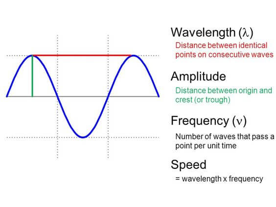
The maximum displacement of wave is called the amplitude of vibration.
During the time period of vibration ‘T’, a wave travels a certain distance in the medium. This distance is defined as the wavelength of the wave and is denoted by the Greek Letter lambda (λ).

credits : https://sites.google.com/a/prc.k12.ms.us/zeringue-s-7th-grade-science/
The speed with which energy is transported between two points in a medium by the motion of waves is known as the velocity of the wave.
V= Distance / time
V= λ/T
V= λf (Since T = 1/f)
λ = V/f
Velocity depends on the density of the material and in the same material it is independent of the frequency of the waves and the material dimensions.
Types of ultrasonic waves :
- Longitudinal waves or compression waves : the particle vibration and the direction of wave propagation is parallel and alternate compression and rarefraction zones are produced by vibration of the particles parallel to the direction of propagation of the wave.
Velocity V(L) is max and propagate in solid, liquid and gas.
- Transverse waves or shear waves: the direction of particle displacement is at right angles or transverse to the direction of wave propagation.
Velocity V(T)= Approx. 50% V (L)
Propagate in solid only.
- Surface wave or Rayleigh wave :here particle vibrations generally follow an elliptical orbit.
Velocity V(S)= 90% V(T)
Propagate in solid only.
- Lamb wave or Plate wave : If a surface wave is introduced into a material that has a thickness equal to or less than wavelength then a plate wave results.
Propagate in solid only.
Acoustic Impedance : the resistance offered to the propagation of an ultrasonic wave by a material is known as the acoustic impedance. It is denoted by ‘Z’ and is determined by multiplying the density ‘ρ’
Of the material by the velocity of the ultrasonic waves in the material.
Z= ρ X V
For normal incidence at an interference
Reflection factor R = (z1-z2)2 / (z1+z2)2
Transmission factor T : 4Z1Z2 / (z1+z2)2
For Oblique incidence
When the ultrasonic beam is incident at an angle to the interface the reflected wave is also at an angle to the surface.
Snell’s Law θ1=θ2
The angle of incidence θ1 is equal to the angle of reflection θ2.

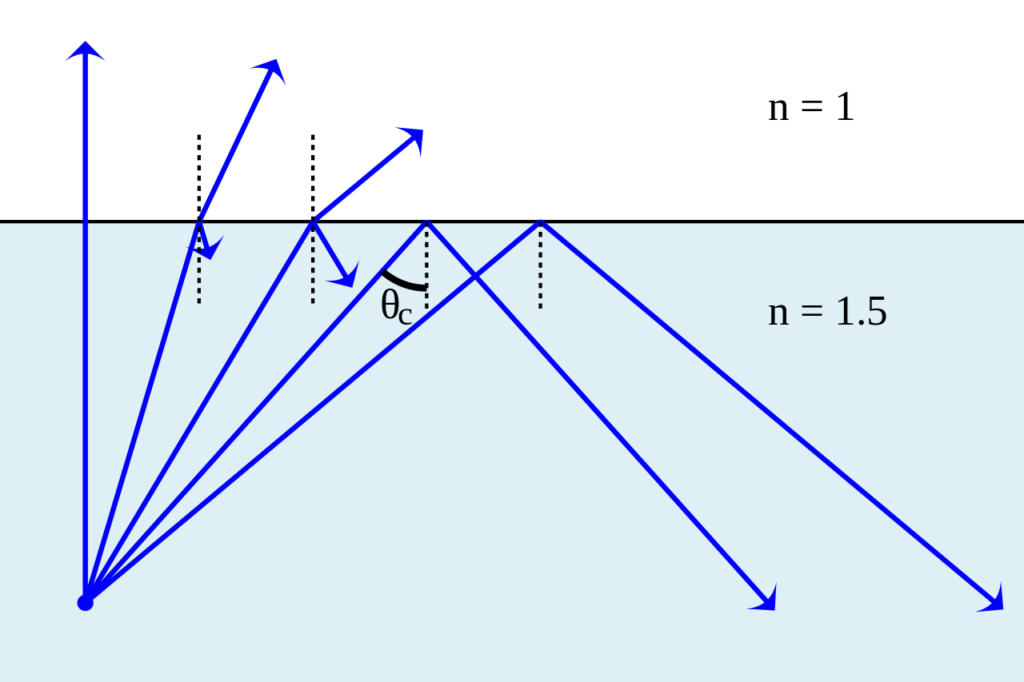
The largest possible angle of incidence which still results in a refracted ray is called the critical angle;
By Lasse Havelund – Own work by uploader, based on other work., CC BY-SA 3.0, https://commons.wikimedia.org/w/index.php?curid=7876641
Refraction : when the ultrasonic beam incident at an angle , the transmitted wave undergoes an abrupt change in the direction and this is known as reflection.

By Josell7 – Own work, CC BY-SA 3.0, https://commons.wikimedia.org/w/index.php?curid=21670922
Sin θ1 /Sin θ2 = V1/V2
But is observed that the reflected wave and the refracted wave consist of two components one of the longitudinal mode and the other of shear mode. This phenomenon is called mode conversion.
Thinner the crystal higher the frequency .
Crystal thickness = λ /2 = V/2f
Near field (Fresnel zone): flaw appearing in the near field must be carefully interpreted because a flaw occurring in this region can produce multiple indications. The amplitude of the reflected signal from the flaw can vary considerably if the effective distance from the probe is effective varies.
Calculation of near field length in UT
N= D2/4 λ (D= diameter of probe)
N= D2f/4V

Determination of beam spread in UT
Sin θ/2 = K λ/d (d= diameter of probe)
Sin θ/2 = K V/d f (K = constant value)
Amplification
Δdb= 20log10 H2/H1 where H1 (actual)and H2(required) are echo height.
For eg. 1:2 = ±6db, 1:10=±20db, 1:100= ±40db
Calculation of maximum penetration thickness for thick wall pipes
T= d(1-Sinθ)/2
Where T= maximum wall thickness
d = outer diameter (OD) of pipe
θ = probe angle
Velocity Correction:

Minimum water path in immersion testing
Min water path = thickness x V(water)/V(specimen) + 6mm
Formulas for using angle probe
½ V = Thickness / Cos θ
V= 2 (½ V) , Minimum range should be 1½ V.
Probe selection :
- General formula 90- thickness, at least two probes shall be used for scanning.
- Based on groove angle:
Probe Angle (Ø) = 90 – α/2
Where, α – Groove angle and Ø- Probe Angle
3. As per AWS:
- 0 – 30 mm Thickness – 700 Probe
- 30 – 40 mm Thickness – 600 Probe
- > 40 mm Thickness – 450 Probe

Credits : https://www.weldingandndt.com/
½ Skip distance : Thickness / tan θ
- Photo by Antoine Dautry on Unsplash
- Wikipedia
- ASNT UT classroom training Book
- ASME BPVC Sec-V
- www.weldingandndt.com
Beam Path(bp) : division where indication is observed x 1 Division value
Surface Distance (sd): bp x sin θ
Depth (d) = bp x cos θ
If Depth > thickness , then 2 Thk-d,
If Depth > 2 thickness, then d-2 Thk

Thanks for sharing knowledge
Dear sir
Thanks for sharing i have one doubt how to find focal point (or) effective beam diameter in PAUT method.
Focal length is controlled by time delays in the PAUT equipment, but regardless it is limited to near field.
Focal Spot size = (Focal length x wavelength)/Active Aperture.
So to reduce spot size use higher freq and large active Aperture
Source: NDT.net
Dear sir provided pcn -level -II selvace data
Ahh Does someone wan to have a closer look at the 1/2 Skip formula?
What is the range formula in ultrasonic testing?
for normal and TR probe range can be simply more than thickness to be inspected. for Angle probe 1/2 V = thick / Cos (probe angle). Range should be kept minimum 1.5V.