This Radiography Test Procedure is written with reference to ASME BPVC Sec-V, Article 2 & 22 for film base radiography of castings and welds with X-rays/Gamma Rays using industrial radiographic film.
To learn more about the basics of Radiography Testing Read our Article INTRODUCTION TO RADIOGRAPHIC TESTING(RT).
To learn more about History of NDT methods, read our blog HISTORY OF NON-DESTRUCTIVE TESTING(NDT)
Note: Whole procedure in one blog can lead to a very long blog, hence the procedure is written in parts.
Surface Preparation
For Casting: Castings Surfaces should not have surface irregularities like dents & surface deformity that the surface irregularities don’t hide the discontinuity or be confused with the image of any discontinuity on the resulting radiograph.

For Welds: The weld ripples or weld surface irregularities on both the inside (where accessible) and outside shall be removed by any suitable process to such a degree that the images of surface irregularities cannot mask or be confused with the image of any discontinuity on the resulting radiograph

Back-scattered Radiation
Radiation which is scattered more than 90 deg with respect to the incident beam, that is, backward in the general direction of the radiation source.

Back Scatter Radiation check
In order to verify excessive backscatter A lead symbol “B,” with minimum dimensions of 7/16 in. (11 mm) in height and 1/16 in. (1.5 mm) in thickness, shall be attached to the back of each film holder during each exposure. The lead symbol “B” shall be placed in a location so that it would appear within an area on the radiograph.

If a light image of the “B,” appears on a darker background of the radiograph, protection from backscatter is insufficient and the radiograph shall be considered unacceptable. However a dark image of the “B” on a lighter background is not cause for rejection.
SYSTEM OF IDENTIFICATION
A system shall be used to produce permanent identification on each radiograph traceable to the
- contract,
- component,
- weld or weld seam, or
- part numbers, as appropriate.

In addition, the Manufacturer’s symbol or name and the date of the radiograph shall be plainly and permanently included on the radiograph. An NDE subcontractor’s name or symbol may also be used together with that of the Manufacturer.
Note: The identification system does not necessarily require that the information appears as radiographic images.
Caution: In any case, this information shall not obscure the area of interest.
INTENSIFYING SCREENS
Intensifying screen: a material that converts a part of the radiographic energy into light or electrons and that, when in contact with a recording medium during exposure, improves the quality of the radiograph, or reduces the exposure time required to produce a radiograph or both.
Types of intensifying Screen:
- Metallic Foil Screens
- Other Metallic Screen Materials
- Fluorescent Screens
Metallic Foil Screen:
- Lead foil screens are commonly used in direct contact with the films, and, depending upon their thickness, and composition of the specimen material.
- screen used in front of the film acts as a filter, absorbing the scattered radiation arising from the specimen, thus improving radiographic quality.
- the back lead screens are used as protection against back-scattered radiation and their thickness is only important for this function.
- For radiography using radioactive sources, the minimum thickness of the front lead screen should be 0.005 in. (0.13 mm) for iridium-192, and 0.010 in. (0.25 mm) for cobalt-60.

The selection of lead screen thickness, or for that matter, any metallic screen thickness, is subject to the considerations as follows
- The material radiographed.
- The thickness of the material radiographed.
- Variation of the thickness of the material radiographed.
- The energy spectrum of the radiation used.
- The improvement desired
Other Metallic Screen Materials
- Lead oxide screens perform in a similar manner to lead foil screens except that their equivalence in lead foil thickness approximates 0.0005 in. (0.013 mm).
- Copper screens have somewhat less absorption and intensification than lead screens but may provide somewhat better radiographic sensitivity with higher energy above 1 MV.
- Gold, tantalum, or other heavy metal screens may be used in cases where lead cannot be used.

Fluorescent Screens
Fluorescent intensifying screens have a cardboard or plastic support coated with a uniform layer of inorganic phosphor (crystalline substance). Phosphors convert photon energy to light. The support and phosphor are held together by a radiotransparent binding material.

Fluorescent screen exposures are usually much shorter than those made without screens or with lead intensifying screens because radiographic films generally are more responsive to visible light than to direct X-radiation, gamma radiation, and electrons.
Caution: All screens should be handled carefully to avoid dents and scratches, dirt, or grease on active surfaces. Screens showing evidence of physical damage should be discarded.
Image Quality Indicator
Image Quality Indicator (IQI) is an indicator of the quality of the radiographic image. IQI’s in a radiograph indicates the overall sensitivity of the technique and providing a measure of how well the radiograph will reveal discontinuities. It is placed on the test specimen in a position where its image will be recorded on the radiograph.
Types of IQI
- Hole Type: a rectangular plaque, made of material radiographically similar to that of the object being radiographed, with small diameter holes (1T, 2T, and 4T) used to check the image quality of the radiograph.
- Wire Type: a set of small diameter wires, made of material radiographically similar to that of the object being radiographed, used to check the image quality of the radiograph.
Hole Type IQI:

Hole-type IQIs shall be manufactured and identified in accordance with the requirements or alternates allowed in SE-1025 Standard Practice for Design, Manufacture, and Material Grouping Classification of Hole-Type Image Quality Indicators ( IQI) Used for Radiology
Note: ASME standard IQI’s shall consist of those in Table T-233.1.

Wire type IQI

Reference: SE 747
Wire-type IQIs shall be manufactured and identified in accordance with the requirements or alternates allowed in SE-747(Standard Practice for Design, Manufacture and Material Grouping Classification of Wire Image Quality Indicators ( IQI) Used for Radiology), except that the largest wire number or the identification number may be omitted.
ASME standard IQIs shall consist of those in Table T-233.2 for wire type.

Selection of IQI
As per ASME BPVC Sec-V,Article 2
Material: IQIs shall be selected from either the same alloy material group or grade as identified in SE- 1025 for hole type or SE-747 for wire type, or from an alloy material group or grade with less radiation absorption than the material being radiographed.
Size: The designated whole IQI or essential wire shall be as specified in Table T-276. A thinner or thicker hole-type IQI may be substituted for any section thickness listed in Table T-276, provided an equivalent IQI sensitivity is maintained.

Ref: ASME BPVC Article 2
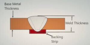
(a) Welds With Reinforcements. The thickness on which the IQI is based is the nominal single-wall material thickness plus the weld reinforcement thickness estimated to be present on both sides of the weld (I.D. and O.D.). The values used for the estimated weld reinforcement thicknesses shall be representative of the weld conditions and shall not exceed the maximum permitted by the referencing Code Section (UW-35 FINISHED LONGITUDINAL AND CIRCUMFERENTIAL JOINTS in ASME SEC-VIII Div-1).
The physical measurement of the actual weld reinforcements is not required. Backing rings or strips shall not be considered as part of the thickness in IQI selection.

CIRCUMFERENTIAL JOINTS
ASME BPVC Sec-VIII Div-1
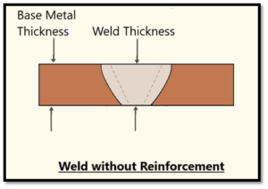
(b) Welds Without Reinforcements. The thickness on which the IQI is based is the nominal single-wall material thickness. Backing rings or strips shall not be considered as part of the thickness in IQI selection.
However with regard to (a) and (b) above, when the actual material/weld thickness is measured, IQI selection may be based on these known values.
Equivalent Hole-Type IQI Sensitivity
Suppose you have to carry out radiography of a job thickness whose IQI as per Table T-276 is not available with you. In such scenarios T-283.2 Equivalent Hole-Type IQI Sensitivity clause gives you an option to use Equivalent Hole type IQI.
A thinner or thicker hole-type IQI than the designated IQI can be used, provided an equivalent or better IQI sensitivity, as listed in Table T-283, is achieved and all other requirements for radiography are met. Equivalent IQI sensitivity is shown in any row of ASME BPVC Article 2 Table T-283 which contains the designated IQI and hole.
Better IQI sensitivity is shown in any row of the Table below which is above the equivalent sensitivity row. If the designated IQI and hole are not represented in the table, the next thinner IQI row from Table T-283 may be used to establish equivalent IQI sensitivity.

Ref : ASME BPVC Article 2
As Per ASME BPVC Sec-V, Article 22
While doing Radiography as per Article 22 The quality level usually required for radiography is 2 % (2-2T when using hole type IQI) unless a higher or lower quality is agreed upon between the purchaser and the supplier.
In Radiography quality level 2-2T the first number of the quality level designation refers to IQI thickness expressed as a percentage of specimen thickness; the second number refers to the diameter of the IQI hole that must be visible on the radiograph, expressed as a multiple of penetrameter thickness, T.
Equivalent I.Q.I. sensitivity—that thickness of I.Q.I. expressed as a percentage of the section thickness radiologically examined in which a 2T hole or 2 % wire size equivalent would be visible under the same radiological conditions.
Calculation of equivalent Sensitivity for hole type IQI:

Where n = thickness of penetrameter expressed in terms of parent material thickness.
For Example :
To find Equivalent sensitivity of 2-2T quality level,
- n=2
- if 2T hole of the IQI is visible on the radiograph
ES = 2 x (√2T/2T)
=2%
If you want to find Value of “n” for a given Hole type IQI, it is given by the formula

“n” value for given IQI and Thickness
Calculation of sensitivity For wire type IQI

Note 1: If IQI’s of material radiographically similar to that being examined are not available, IQI’s of the required dimensions but of a lower-absorption material may be used.
Note 2: The quality level required using wire IQI’s shall be equivalent to the 2-2T level of Practice E1025 unless a higher or lower quality level is agreed upon between purchaser and supplier.
RADIOGRAPHIC DENSITY
film density: The quantitative measure of diffuse optical light transmission (optical density, blackening) through a developed film.

Density Limitations
The transmitted film density through the radiographic image of the body of
The designated hole-type IQI adjacent to the essential hole or adjacent to the essential wire of a wire-type IQI and the area of interest shall be
- 1.8 minimum for single film viewing for radiographs made with an X-ray source
- 2.0 minimum for radiographs made with a gamma-ray source.
- 1.3 minimum density in each film of for composite viewing of multiple film exposures, each
- The maxim.um density shall be 4.0 for either single or composite viewing.
A tolerance of 0.05 in density is allowed for variations between densitometer readings.
composite viewing: the viewing of two or more superimposed
radiographs from a multiple film exposure.
Density Variation
(a)The density of the radiograph anywhere through the area of interest shall not
- vary by more than minus 15% or plus 30% from the density through the body of the designated hole-type IQI adjacent to the essential hole or adjacent to the essential wire of a wire-type IQI,
- exceed the minimum/maximum allowable density ranges as provided above when calculating the allowable variation in density, the calculation may be rounded to the nearest 0.1 within the range specified above.
(b) When the requirements of (a) above are not met, then an additional IQI shall be used for each exceptional area or areas and the radiograph retaken.
(c) When shims are used with hole-type IQIs, the plus 30% density restriction of (a) above may be exceeded, and the minimum density requirements given above do not apply for the IQI, provided the required IQI sensitivity mentioned below are met.
Required Sensitivity
- Radiography shall be performed with a technique of sufficient sensitivity to display the designated hole-type IQI image and the essential hole, or the essential wire of a wire-type IQI as required in table T- 276 or Table T-283 in case of using equivalent IQI.
- The radiographs shall also display the IQI identifying numbers and letters, which means ASTM, Material group number for ex. 1B and largest wire diameter for example 11 should be visible in the radiograph.
- While using composite film viewing method if the designated hole-type IQI image and essential hole, or essential wire of a wire-type IQI, do not show on any film in a multiple film technique, but do show in composite film viewing, interpretation shall be permitted only by composite film viewing.
- For wire-type IQIs, the essential wire shall be visible within the area of interest representing the thickness used for determining the essential wire, inclusive of the allowable density variations described above.
MONITORING DENSITY OF RADIOGRAPHS
Density of Radiographs shall be monitored using
- Densitometer: a device for measuring the optical density of radiograph film.
or
- step wedge comparison film: a radiographic image of a mechanical step wedge with precise thickness increments and may be used to correlate optical film density to the thickness of the material, also known as a step tablet.

Source: wikipedia

Calibration of Densitometers
Densitometers shall be calibrated at least every 3 months during use as follows:
- A national standard step tablet or a step wedge calibration film, traceable to a national standard step tablet and having at least five steps with neutral densities from at least 1.0 through 4.0, shall be used.
- The step wedge calibration film shall have been verified within the last year by comparison with a national standard step tablet unless, prior to first use, it was maintained in the original light-tight and waterproof sealed package as supplied by the manufacturer.
- Step wedge calibration films may be used without verification for one year upon opening, provided it is within the manufacturer’s stated shelf life.
- The densitometer manufacturer’s step-by-step instructions for the operation of the densitometer shall be followed.
- The density steps closest to 1.0, 2.0, 3.0, and 4.0 on the national standard step tablet or step wedge calibration film shall be read.
- The densitometer is acceptable if the density readings do not vary by more than ±0.05 density units from the actual density stated on the national standard step tablet or step wedge calibration film.
Note: Periodic calibration verification checks shall be performed as described at the beginning of each shift, after 8 hr of continuous use, or after the change of apertures, whichever comes first.
Calibration of Step wedge comparison films
Step wedge comparison films shall be verified prior to first use unless performed by the manufacturer, as follows:
(a) The density of the steps on a step wedge comparison film shall be verified by a calibrated densitometer.
(b) The step wedge comparison film is acceptable if the density readings do not vary by more than ±0.1 density units from the density stated on the step wedge comparison film.
Verification checks shall be performed annually for Periodic Verification.
Quick Tip: as mentioned above that step wedge comparison films are only to be calibrated when then manufacturer doesn’t provide you calibration certificate. Usually, all the manufacturers provide calibration certificates of the step wedge comparison film and are used for periodic calibration of Densitometers.
We have not covered all the important radiography steps in this apart do read Part 2 for the complete procedure.
References:
ASME BPVC Sec-V 2019
- Article 1
- Article 2
- Article 22, SE-94
ASME BPVC Sec-VIII Div-1
https://www.twi-global.com/technical-knowledge/published-papers/novel-method-of-recording-cooling-curves-during-laser-laser-arc-hybrid-welding-may-2003- http://ndttechnology.blogspot.com/2009/01/image-quality-indicators.html


Hello there! This blog post could not be written much better! Going through this article reminds me of my previous roommate! He constantly kept preaching about this. I am going to forward this post to him. Fairly certain he’s going to have a good read. Many thanks for sharing!
Thanks for the blog.Really looking forward to read more.
I really liked your article. Fantastic.