ASME B16.34 Valves–Flanged, Threaded, and Welding End covers pressure-temperature ratings, dimensions, tolerances, materials, nondestructive examination requirements, testing, and marking for cast, forged, and fabricated flanged, threaded, and welding end and wafer or flangeless valves of steel, nickel-base alloys, and other alloys shown in Table 1. Here in this article, we will learn about Radiography (RT) as per ASME B16.34.
ASME B16.34 does not require NDE as mandatory on cast valve bodies for standard class valves. However, Special class valves do require mandatory NDE as specified in Clause 8 of B16.34. Special class valves are valves that have been assigned a higher pressure temperature rating that would normally be permitted by the standard on the basis of this additional examination. For example, a Class 150 valve can be a Class 150 “Standard Class” or a Class 150 “Special Class”. The special class is still called Class 150 but has a different rating. These ratings are tabulated in ASME B16.34.
GENERAL
Nondestructive examinations shall be performed on the cast, forged, rolled, wrought, or fabricated material after heat treatment required by the material specification either prior to or after the finish machining at the option of the manufacturer. Surfaces shall be clean and free of surface conditions that may mask unacceptable indications. Accessible surfaces (see paras. 8.3.1.2 and 8.3.2.2) do not include threads, drilled or threaded holes, for example, for bolting, packing, stems, or auxiliary connections.
Surface Examination
All exterior and all accessible interior surfaces of body, bonnet, and cover castings shall be given a surface examination. Table 1, Group 1 materials in ASME B16.34 shall be given either a magnetic particle examination or a liquid penetrant examination. Table 1, Groups 2 and 3 materials in ASME B16.34 shall be given a liquid penetrant examination. Magnetic particle examinations shall be in accordance with the procedure and acceptance standards of ASME B16.34 Mandatory Appendix II. Liquid penetrant examinations shall be in accordance with the procedure and acceptance standards of ASME B16.34 Mandatory Appendix III
Radiography coverage
Radiography examination The radiographic procedures and acceptance standards to be used shall be in accordance with ASME B16.34 Mandatory Appendix I. Body and bonnet or cover sections requiring radiography are as given in this paragraph and as shown typically in Figures 7 through 17. For body and bonnet configurations not represented, it is permissible to construct a composite coverage area based on these illustrations and the descriptions that follow. The distance ‘A’ over which film coverage is required is expressed in multiples of tm where tm is the minimum wall thickness requirement as determined by ASME B16.34 para. 6.1. The value for film coverage of A is intended to be the greater of 3tm or 70 mm (2.75 in.).
It should be recognized, however, that in some cases the specified value of A will exceed the intent of the film coverage area as illustrated in Figures 7 through 17. For example, in Figure 12 the body neck or run sections may not accommodate the full value of A as defined. In such cases, the requirement may be satisfied by providing film coverage substantially as shown in the sketches. Also, if the full defined coverage width A would result in the film running substantially into an adjacent fillet or crotch section, the value of A may be reduced to a practical maximum value. Small variations in coverage are permitted when necessary to accommodate standard film sizes.
Film coverage shall include the following areas:
(a) Body
- a band around each weld end extending back from the body end a distance equal to the greater of 3tm or 70 mm (2.75 in.)
- a band around the bonnet neck extending down from the top of the body on pressure seal valves and from the back of the flange on bolted bonnet valves a distance equal to the greater of 3tm or 70 mm (2.75 in.)
- a band in the area of the junction between each seat and body shell having a width equal to the greater of 3tm or 70 mm (2.75 in.) and an encompassing girth extending between the fillets of the intersecting sections, e.g., as shown approximately 210 deg for Figure 7
(b) Bonnet.
The junction of the stem seal chamber with the bonnet closure plate or flange.
(c) Cover
- volumetric examination is not required for flat covers with or without raised faces
- for dished covers, a band in the vicinity of the junction between the dished and flanged sections having a width equal to the greater of 3tm or 70 mm (2.75 in.)


Note: The distance ‘A’ over which film coverage is required is expressed in multiples of tm where tm is the minimum wall thickness requirement as determined by ASME B16.34 para. 6.1. The value for film coverage of A is intended to be the greater of 3tm or 70 mm (2.75 in.).
Radiography Procedure
- ASTM E94, Standard Guide for Radiographic Examination, shall be used as a guide.
- The film shall be as close as practical to the part being radiographed.
- Any commercially available intensifying screen, except those of the fluorescent type, may be used.
- All film shall bear identification markers to properly orient the film for interpretation and to denote the actual part under examination.
- Film shall be marked to identify the organization producing the radiograph and the date exposed.
- Penetrameters shall be used on each radiograph. Penetrameters shall conform to the requirements of ASTM E94.
- Any commercially available film may be used, provided it is equal to or finer-grained than Type 2, ASTM E94.
- The manufacturer, at his option, may use a double film technique and a combination of a single and double viewing so as to cover a greater latitude in part thickness with a single exposure.
- Radiographs shall be within the following photographic (H&D) density range: single film viewing — 1.5 min., 4.0 max.
- superimposed viewing of double film, each single film — 1.00 min., 2.5 max., with a double film — 4.0 max.
- Surfaces shall be such that radiographic contrast due to surface condition cannot mask or be confused with that of any defect.
- Single-wall thickness shall be radiographed wherever practical.
- The radiographic sensitivity shall be 2 – 4T for thickness up to and including 19 mm (0.75 in.) and 2 – 2T for thickness greater than 19 mm (0.75 in.).
Acceptance criteria
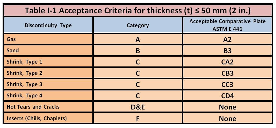
- For wall thickness t ≤50 mm (t ≤ 2 in.) the comparative plates of ASTM E446 define acceptable indications as shown in Table I-1.
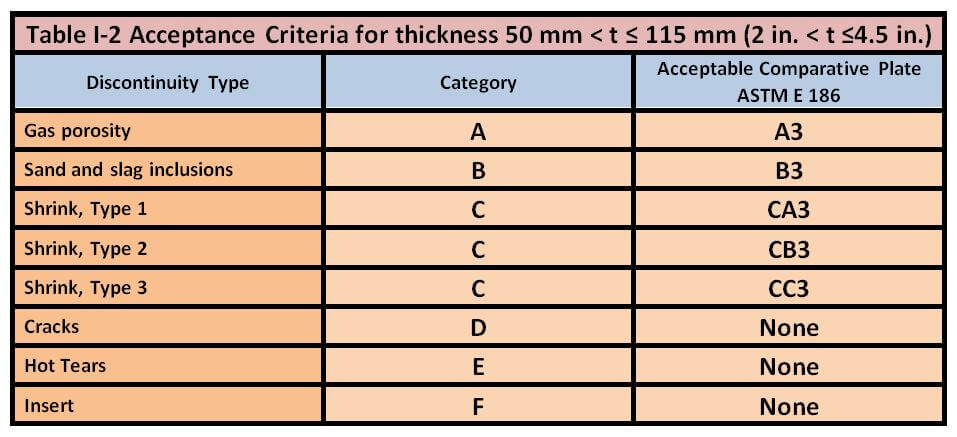
- For wall thickness 50 mm < t ≤ 115 mm (2 in. < t ≤ 4.5 in.) the comparative plates of ASTM E186 define acceptable indications as shown in Table I-2.
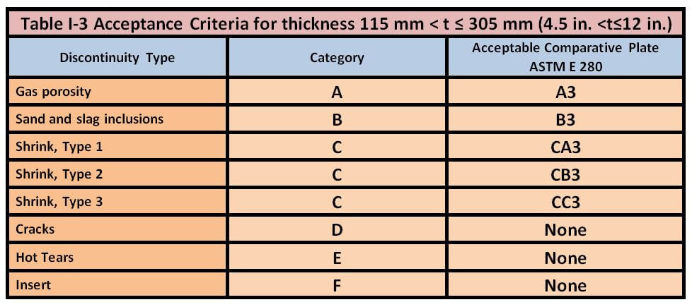
- For wall thickness 115 mm < t ≤ 305 mm (4.5 in. < t ≤ 12 in.) the comparative plates of ASTM E280 define acceptable indications as shown in Table I-3.


NDE after repair by welding-
- The area is re-examined by the NDE method that originally disclosed the defect. The re-examination by magnetic particle or liquid penetrant methods of a repaired area originally disclosed by magnetic particle or liquid penetrant examination shall be performed after post-weld heat treatment when post-weld heat treatment is performed. The re-examination by radiography or ultrasonic methods of a repaired area originally disclosed by radiography or ultrasonic examination may be performed either before or after post-weld heat treatment when post-weld heat treatment is performed. The acceptance standards shall be as in the original examination.
- Weld repairs made as a result of radiographic examination shall be radiographed after welding. The acceptance standards for porosity and slag inclusion in welds shall be in accordance with the ASME Boiler and Pressure Vessel Code, Section VIII, Division 1, UW-51.
To learn about complete radiography test procedure read our blogs:
To learn about the basics of radiography testing read our blog:
References :
- ASME B16.34 Valves – Flanged, Threaded, and Welding End,
- ASTM E-94 Standard Guide for Radiographic Examination Using Industrial Radiographic Film,
- ASME Boiler and Pressure Vessel Code, Section VIII, Division 1, UW-51,
- https://www.asme.org/codes-standards/find-codes-standards/b16-34-valves-flanged-threaded-welding-end
- https://www.eng-tips.com/
- Feature Photo by Mika Baumeister on Unsplash

Good