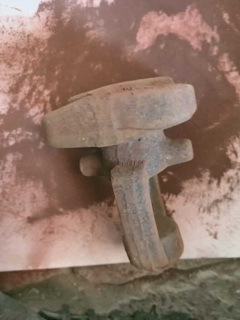
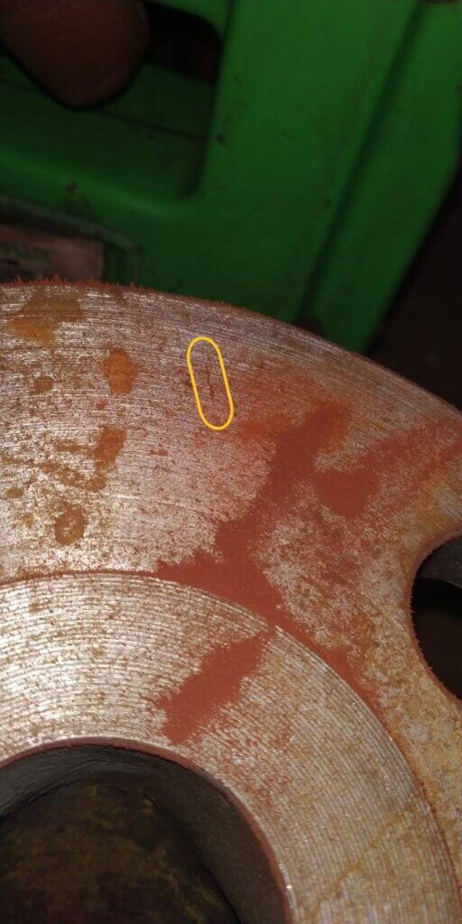
The magnetic particle examination NDT method is applied to detect cracks and other discontinuities on the surface/slightly subsurface of ferromagnetic materials. The sensitivity is greatest for surface discontinuities and diminishes rapidly with increasing depth of discontinuities below the surface. Typical types of discontinuities that can be detected by this method are cracks, laps, seams, cold shuts, and laminations.
To learn basics of Magnetic Particle Examination, Read our blog:
Introduction to Magnetic Particle Testing(MT)
Surface Condition preparation of Test Surface
- Surfaces in as-welded, as-rolled, as-cast, or as forged conditions results are obtained Satisfactory usually. However, surface preparation by grinding or machining may be necessary where surface irregularities could mask indications due to discontinuities.
- Prior to magnetic particle examination, the surface to be examined and all adjacent areas within at least 1 in. (25 mm) shall be dry and free of all dirt, grease, lint, scale, welding flux and spatter oil, or other extraneous matter that could interfere with the examination.
- detergents, organic solvents, descaling solutions, paint removers, vapor degreasing, sand or grit blasting, or ultrasonic cleaning methods may be used for cleaning.
- If nonmagnetic coatings are left on the part in the area being examined, it shall be demonstrated that indications can be detected through the existing maximum coating thickness applied. When the AC yoke technique is used, the demonstration shall be in accordance with Mandatory Appendix I of ASME BPVC Sec-V Article 7.
Nonmagnetic Surface Contrast Enhancement
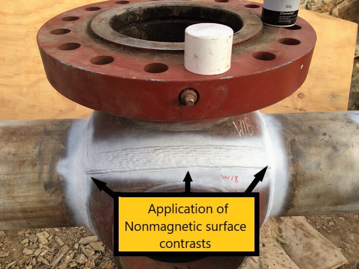
When there is poor color contrast between Testing material and the test surface. Nonmagnetic surface contrasts may be applied by the examiner to uncoated surfaces, only in amounts sufficient to enhance particle contrast. When nonmagnetic surface contrast enhancement is used, it shall be demonstrated that indications can be detected through the enhancement. Thickness measurement of this nonmagnetic surface contrast enhancement is not required

White Contrast paint for MT 
YOKE TECHNIQUE
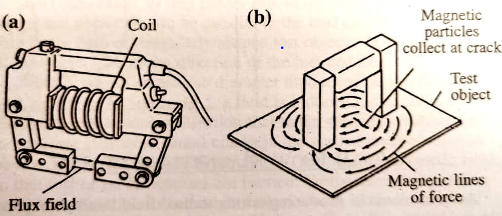
A longitudinal magnetic field can be induced in a test object or in a limited area of a test object using a hand held yoke. For this technique, alternating or direct current electromagnetic yokes, or permanent magnet yokes shall be used.
CALIBRATION
Light Meters
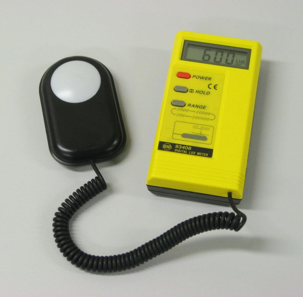
Light meters shall be calibrated at least once a year or whenever a meter has been repaired. If meters have not been in use for one year or more, calibration shall be done before being used.

Lux Meter
Credits : wikipedia
LIFTING POWER OF YOKES
- The magnetizing power of yoke shall be verified prior to use each day the yoke is used and whenever the yoke has been damaged or repaired.
- Each alternating current (AC )electromagnetic yoke shall have a lifting power of at least 10 lb (4.5 kg) at the maximum pole spacing, with contact similar to what will be used during the examination.
- Each direct current (DC) or permanent magnetic yoke shall have a lifting power of at least 40 lb (18 kg) at the maximum pole spacing, with contact similar to what will be used during the examination.
Note : Each weight shall be weighed with a scale from a reputable manufacturer and stenciled with the applicable nominal weight prior to first use. A weight need only be verified again if damaged in a manner that could have caused a potential loss of material.
Magnetic Field Adequacy.
Pie-Shaped Magnetic Particle Field Indicator. The indicator, shown in Figure T-764.2(a), shall be positioned on the surface to be examined, such that the copper-plated side is away from the inspected surface. Suitable field strength is indicated when a clearly defined line (or lines) of magnetic particles form(s) across the copper face of the indicator when the magnetic particles are applied simultaneously with the magnetizing force.


EXAMINATION MEDIUM
The finely divided ferromagnetic particles used for the examination shall meet the following requirements.
- Particle Types – The particles shall be treated to impart color (fluorescent pigments, nonfluorescent pigments, or both) in order to make them highly visible (contrasting) against the background of the surface being examined.
- Particles – Dry and wet particles and suspension vehicles shall be in accordance with the applicable specifications listed in SE-709, para. 2.2.
- Temperature Limitations – Particles shall be used within the temperature range limitations set by the manufacturer of the particles.
METHOD OF EXAMINATION
The ferromagnetic particles used in an examination medium can be either wet or dry, and may be either fluorescent or non fluorescent. Examination(s) shall be done by the continuous method.
Dry Particles
The magnetizing current shall remain on while the examination medium is being applied and while any excess of the examination medium is removed.
Wet Particles
The magnetizing current shall be turned on after the particles have been applied. The flow of particles shall stop with the application of current. Application of Wet particles from aerosol spray cans or pump sprayers may be done before and/or during magnetizing current application. Also, wet particles may be applied during the application of magnetizing current if they are not applied directly to the examination area and are allowed to flow over the examination area or are applied directly to the examination area with low velocities insufficient to remove accumulated particles.
WET PARTICLE CONCENTRATION AND CONTAMINATION
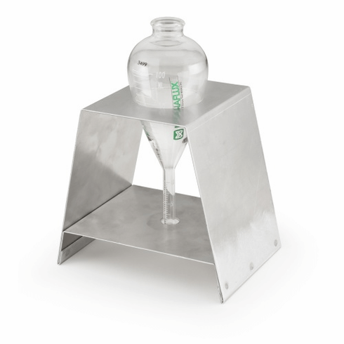
Wet Horizontal Units shall have the bath concentration and bath contamination determined by measuring its settling volume. This is accomplished through the use of a pear-shaped centrifuge tube with a 1-mL stem (0.05-mL divisions) for fluorescent particle suspensions or a 1.5-mL stem (0.1-mL divisions) for nonfluorescent suspensions
Before sampling,the suspension should be run through the recirculating system for at least 30 min to ensure thorough mixing of all particles which could have settled on the sump screen and along the sides or bottom of the tank.
Concentration
Take a 100-mL portion of the suspension from the hose or nozzle, demagnetize and allow it to settle for approximately 60 min with petroleum distillate suspensions or 30 min with water-based suspensions before reading. The volume settling out at the bottom of the tube is indicative of the particle concentration in the bath.
Settling Volumes.
For fluorescent particles, the required settling volume is from 0.1 mL to 0.4 mL in a 100-mL bath sample and from 1.2 mL to 2.4 mL per 100 mL of the vehicle for nonfluorescent particles unless otherwise specified by the particle manufacturer. Concentration checks shall be made at least every eight hours.
Contamination
Both fluorescent and nonfluorescent suspensions shall be checked periodically for contaminants such as dirt, scale, oil, lint, loose fluorescent pigment, water (in the case of oil suspensions), and particle agglomerates which can adversely affect the performance of the magnetic particle examination process. The test for contamination shall be performed at least once per week.
(a) Carrier Contamination: For fluorescent baths, the liquid directly above the precipitate should be examined with fluorescent excitation light. The liquid will have a little fluorescence. Its color can be compared with a freshly made-up sample using the same materials or with an unused sample from the original bath that was retained for this purpose. If the “used” sample is noticeably more fluorescent than the comparison standard, the bath shall be replaced.
(b) Particle Contamination: The graduated portion of the tube shall be examined under fluorescent excitation light if the bath is fluorescent and under visible light (for both fluorescent and nonfluorescent particles) for striations or bands, differences in color, or appearance. Bands or striations may indicate contamination. If the total volume of the contaminates, including bands or striations exceeds 30% of the volume magnetic particles, or if the liquid is noticeably fluorescent, the bath shall be replaced.
EXAMINATION
PRELIMINARY EXAMINATION: Before the magnetic particle examination is conducted, a check of the examination surface shall be conducted to locate any surface discontinuity openings which may not attract and hold magnetic particles because of their width.
DIRECTION OF MAGNETIZATION : At least two separate examinations shall be performed on each area. During the second examination, the lines of magnetic flux shall be approximately perpendicular to those used during the first examination
Note : Regardless of the inspection technique the yoke shall never be used with a leg spacing of less than 2”
EXAMINATION COVERAGE: All examinations shall be conducted with sufficient field overlap to ensure 100% coverage of the area to inspect with the required sensitivity.
EXCESS PARTICLE REMOVAL: Accumulations of excess dry particles in examinations shall be removed with a light air stream from a bulb or syringe or other sources of low-pressure dry air. The examination current or power shall be maintained while removing the excess particles.
INTERPRETATION
The interpretation shall identify if an indication as false, nonrelevant, or relevant. False and nonrelevant indications shall be proven as false or nonrelevant. Interpretation shall be carried out to identify the locations of indications and the character of the indication.
Visible (Color Contrast) Magnetic Particles.
- Surface discontinuities are indicated by accumulations of magnetic particles which should contrast with the examination surface. The color of the magnetic particles shall be different than the color of the examination surface.
- Illumination (natural or supplemental white light) of the examination surface is required for the evaluation of indications. The minimum light intensity shall be 100 fc (1076 lx).
- The light intensity, natural or supplemental white light source, shall be measured with a white lightmeter prior to the evaluation of indications or a verified light source shall be used. Verification of light sources is required to be demonstrated only one time, documented, and maintained on file.
Fluorescent Magnetic Particles.
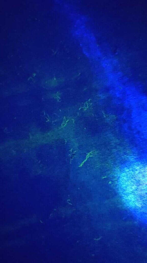
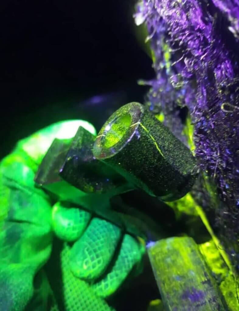
With fluorescent magnetic particles, the process is essentially the same as above, with the exception that the examination is performed using ultraviolet light, called UV-A light. The examination shall be performed as follows:
- It shall be performed in a darkened area with a maximum ambient white light level of 2 fc (21.5 lx) measured with a calibrated white light meter at the examination surface.
- Examiners shall be in a darkened area for at least 5 min prior to performing examinations to enable their eyes to adapt to dark viewing. Glasses or lenses worn by examiners shall not be photosensitive.
- The examination area shall be illuminated with UV-A lights that operate in the range between 320 nm and 400 nm.
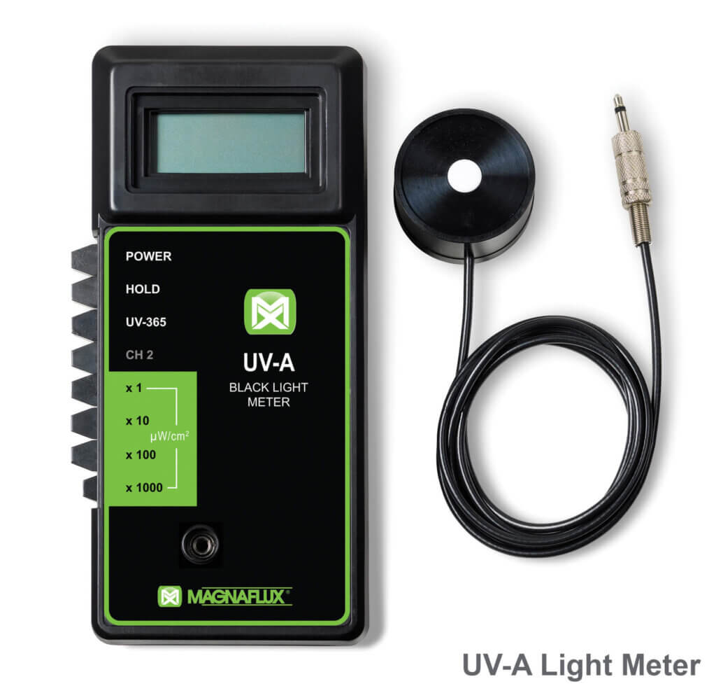
- UV-A lights shall achieve a minimum of 1000 μW/cm2 on the surface of the part being examined throughout the examination.
- Reflectors, filters, glasses, and lenses should be checked and, if necessary, cleaned prior to use. Cracked or broken reflectors, filters, glasses, or lenses shall be replaced immediately.
- The UV-A light intensity shall be measured with a UV-A light meter prior to use, whenever the light’s power source is interrupted or changed, and at the completion of the examination or series of examinations.
- Mercury vapor arc lamps produce UV-A wavelengths mainly at a peak wavelength of 365 nm for inducing fluorescence. LED UV-A sources using a single UV-A LED or an array of UV-A LEDs shall have emission characteristics comparable to those of other UV-A sources.
DEMAGNETIZATION: When residual magnetism in the part could interfere with subsequent processing or usage. The part shall be demagnetized any time after completion of the examination.
POST-EXAMINATION CLEANING: When post-examination cleaning is required. It should be conducted as soon as practical using a process that does not adversely affect the part.
EVALUATION
- All indications shall be evaluated in terms of the acceptance standards of the referencing Code Section.
- Discontinuities on or near the surface are indicated by retention of the examination medium. However, localized surface irregularities due to machining marks or other surface conditions may produce false indications.
- Broad areas of particle accumulation, which might mask indications from discontinuities, are prohibited.such areas shall be cleaned and reexamined.
RECORDING OF INDICATIONS
- Nonrejectable Indications – Nonrejectable indications shall be recorded as specified by the referencing code Section.
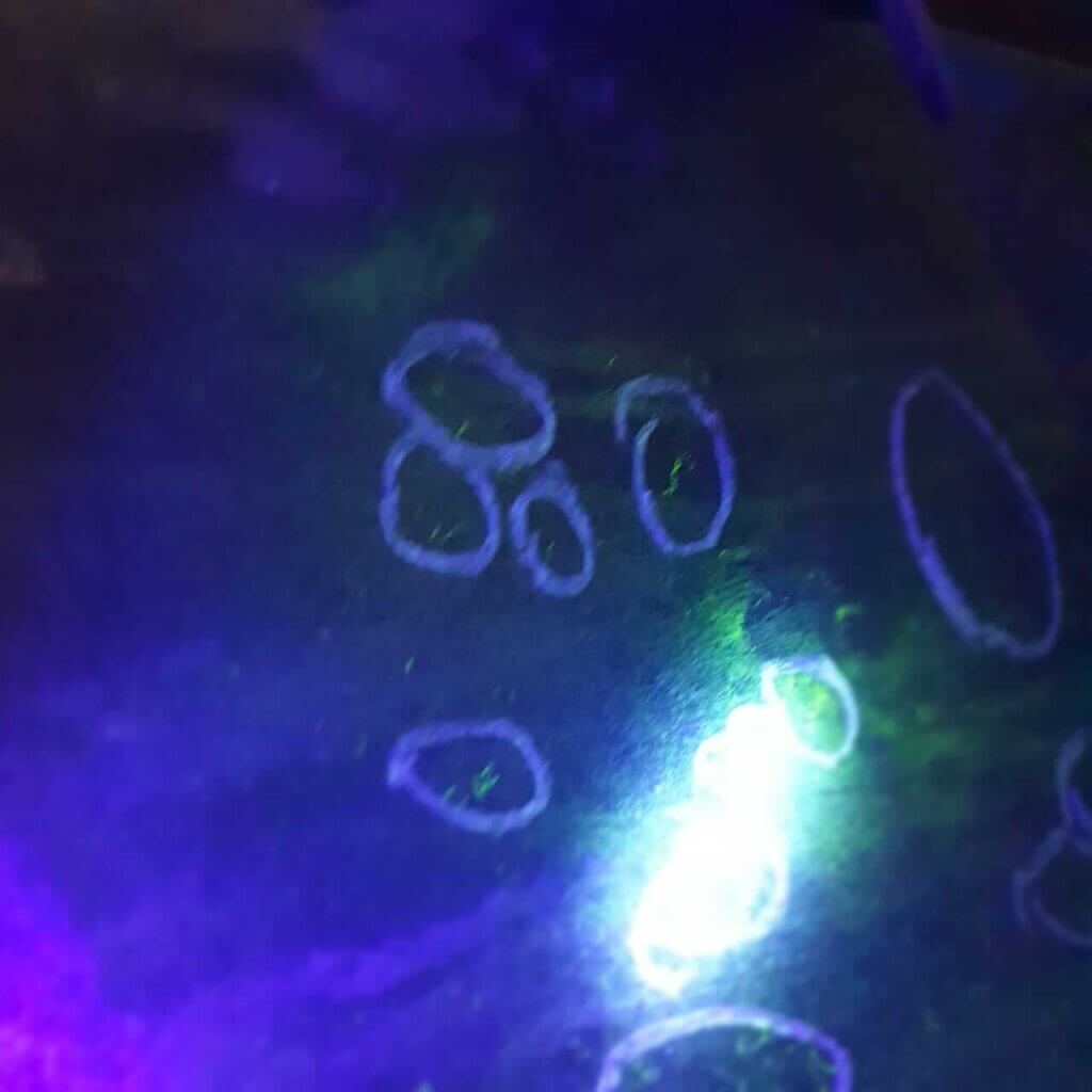
- Rejectable Indications – Rejectable indications shall be recorded. As a minimum, the type of indications (linear or rounded), location and extent (length or diameter or aligned) shall be recorded.
EXAMINATION RECORDS
following information shall be recorded, for each examination:
- the requirements of Article 1, T-190(a)
- magnetic particle equipment and type of current
- magnetic particles (visible or fluorescent, wet or dry)
- map or record of indications (Nonrejectable Indications and Rejectable Indications )
- material and thickness
- lighting equipment


An excellent post, congratulations !!